Overview of CAEPIPE 3D+
Pipe stress software CAEPIPE 3D+ has two (2) parts built-in as listed below.
Part 1 generates pipe stress models in CAEPIPE 3D+ format from:
- Plant database of 3D Plant Design software E3D/PDMS and CADMATIC, and
- PCF files generated from plant database of 3D Plant Design software such as SmartPlant, AutoCAD Plant 3D, AutoPlant, CATIA, CADWORX, etc.
by reading the following from the plant database / PCF files of the above 3D Plant Design software:
- Piping geometry, pipe sections and material properties
- Temperature, pressure and weight of pipe fittings
- Thermal anchor movements at equipment nozzles
- Allowable loads at equipment nozzles
- Pipe support details to create the corresponding hangers, guides, etc. in CAEPIPE 3D+.
Part 2 of CAEPIPE 3D+ is the same as the full-fledged internationally accepted pipe stress software CAEPIPE, which reads the stress models generated through Part 1. For modeling and analysis features of CAEPIPE, review CAEPIPE User's Manual, Technical Reference Manual and Code Compliance Manual available at the link Caepipe Doc
Download CAEPIPE 3D+ Now
Why CAEPIPE 3D+?
It is common practice worldwide that piping layout designers route pipes in 3D Plant Design systems with consideration given mainly to space constraints, process and flow constraints and other requirements arising from constructability, operability and repairability. Most often, pipe stress requirements are not sufficiently considered.
In order to meet pipe stress requirements, pipe stress engineers have all along felt the following needs.
CAEPIPE 3D+ Features
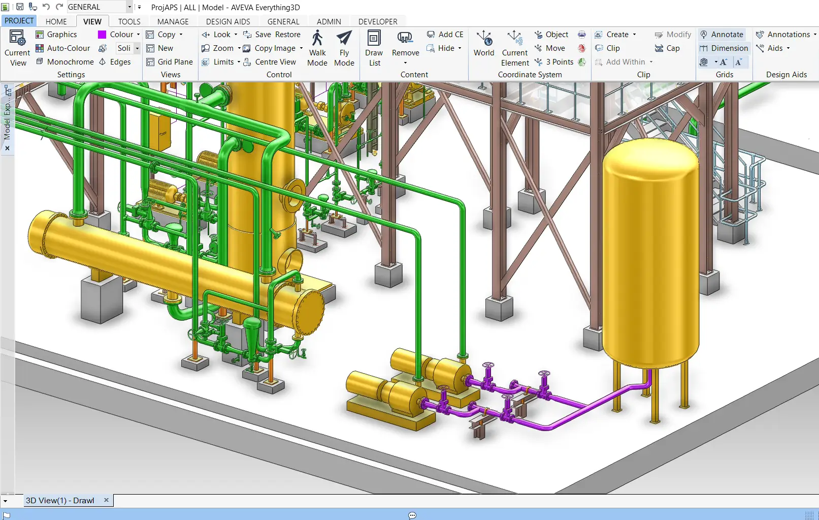
Stress Model generated by Designer from 3D Plant Design System

How CAEPIPE 3D+ Works
Each licensed seat of CAEPIPE 3D+ currently allows the use of the following 5 modules, with the only restriction being only one module can be used at any point in time. As listed below, CAEPIPE 3D+ can be used as a stand-alone CAEPIPE in case 3D plant database or PCF files are not available to work with.
CAEPIPE 3D+ for E3D/PDMS*
CAEPIPE 3D+ for CADMATIC*
CAEPIPE 3D+ for PDS
CAEPIPE 3D+ for PCF files generated by 3D Plant Design Systems such as SmartPlant, AutoCAD Plant 3D, AutoPlant, CATIA, CADWORX etc.
CAEPIPE (stand-alone)
In short, all five modules are available for use by a licensed CAEPIPE 3D+ seat, but only one module at any point in time.
*CAEPIPE 3D+ runs as an on-line, add-on module to E3D/PDMS/CADMATIC, whereby a 3D piping designer transfers piping layouts and all available data from E3D/PDMS/CADMATIC to CAEPIPE 3D+ directly and performs first-level stress compliance checks without exiting E3D/PDMS/CADMATIC. Similarly, a pipe stress engineer performs detailed analyses of stress models received from the 3D piping designer without exiting E3D/PDMS/CADMATIC.
The same full-fledged pipe stress software CAEPIPE 3D+ is used with many 3D Plant Design systems or as a stand-alone stress software, based on the requirements of projects.
CAEPIPE 3D+ input files can be generated directly from 3D Plant Design systems, thereby saving time and avoiding errors in re-creating stress models manually.
CAEPIPE 3D+ can be used first by 3D piping designers as a first-level piping flexibility check software. This step substantially reduces the number of design iterations between the piping layout and stress departments, resulting in huge time saving during design.
Using CAEPIPE 3D+ module for E3D/PDMS/CADMATIC, 3D piping designers can check for interference between “piping deformed under hot operating condition” and adjacent objects.
When CAEPIPE 3D+ is used on E3D/PDMS/CADMATIC, 3D plant model can be instantly viewed by 3D designers during their first-level stress checks and by pipe stress engineers during detailed analyses.
Stress analysts can identify all possible locations for pipe supports on 3D plant model, as it contains all supporting objects such as steel and concrete structures adjacent to the concerned piping systems. These possible pipe support locations, once marked in the 3D plant model, are automatically transferred as “nodes” in the CAEPIPE 3D+ input files.
Piping designers can import layout changes made by stress engineers into 3D plant model and update pipe supports by viewing final stress models, resulting in significant time saving during design.
In summary, CAEPIPE 3D+ helps 3D piping designers and stress engineers to arrive at substantially better piping layouts that also meet all stress requirements, thereby saving costs associated with design, materials, construction, operation and maintenance.
CAEPIPE provides an advanced, fully integrated analysis platform that solves both linear and nonlinear problems across a wide range of loading conditions.
Static Analysis
CAEPIPE offers a wide range of static analysis capabilities to address real-world loading conditions. It accounts for deadweight of piping and components, multiple thermal load and pressure scenarios (supporting up to 10 each), and additional loads such as hydrotest, snow or ice accumulation, internal linings, and cladding. The software allows engineers to incorporate support displacements caused by foundation settlement or nozzle movements. It can also simulate static equivalent loads from seismic and wind events, wave loading for offshore applications, and perform specialized analyses for buried piping systems.
Dynamic Analysis
Dynamic behaviour of piping systems can be thoroughly evaluated in CAEPIPE. It includes modal analysis to identify natural frequencies up to 9999 Hz. Engineers can perform response spectrum analysis - either uniform or multi-level - as well as time history simulations using the Wilson-θ integration method. The software supports harmonic excitation studies and fluid transient effects, including pressure relief valve (PRV) events, fluid hammer, and slug flow. For impulsive loading scenarios, CAEPIPE provides force spectrum analysis to capture system response accurately.
Equipment and Pressure Design Codes
CAEPIPE supports a wide range of equipment design codes to ensure reliable nozzle load compliance. For pumps, it follows API 610 and ANSI/HI 9.6.2 standards. Compressors are covered under API 617, and air-cooled heat exchangers use API 661. Steam turbines are evaluated using NEMA SM-23. For pressure vessels and nozzle-to-shell connections, CAEPIPE supports ASME Section VIII Division 2 and WRC 537. It also includes European standards like EN 13445 and EN 13480-3 for unfired pressure vessels and for piping systems respectively. These codes help assess the structural integrity of equipment under piping-induced loads.
Corrosion and Fatigue:
CAEPIPE provides tools for assessing corrosion and fatigue in piping systems. It evaluates remaining strength of corroded pipes using ASME B31G. For fatigue, CAEPIPE performs both simplified fatigue evaluation as required by applicable piping codes, and detailed fatigue evaluation following the guidelines of ASME Section VIII Division 2.
Global Piping Code Compliance
ASME: B31.1, B31.3, B31.4, B31.5, B31.8, B31.9, B31.12, Section III NC/ND
EN / ISO: EN 13480-3, EN 13941-1, EN 1998-1, ISO 14692-3
National Codes: RCC-M, CODETI, IGEM (UK), BS 806, DNV-ST-F101, Z662 (Canada), Stoomwezen (Netherlands)
CAEPIPE 3D+, if used as CAEPIPE on a stand - alone basis, streamlines modelling with its unique Layout Window, where piping elements are entered row-wise like scripting. This allows users to model without drag-and-drop, and instead use concise text commands and shortcuts:
Shortcut-based Modelling
CAEPIPE allows users to create and edit piping models using simple keyboard shortcuts and intuitive commands - instead of relying entirely on graphical drag-and-drop or mouse input. This significantly speeds up model creation, especially for large and repetitive piping layouts.
Key Benefits:
Faster Input: You can define long runs of pipe, elbows, supports, valves, reducers, etc., using single-letter commands (like B for bend, R for reducer, A for anchor).
Minimal Mouse Use: Most actions can be completed directly from the keyboard, which is particularly helpful for power users and experienced engineers.
Copy/Paste Efficiently: You can duplicate parts of your model or reuse sub-models by simply copying rows and pasting them elsewhere.
Quick Editing: You can edit coordinates, properties, and loads directly in the spreadsheet-like layout - as fast as editing an Excel sheet.
Unique Features of CAEPIPE 3D+
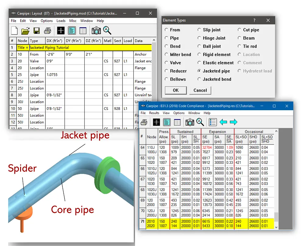
Jacketed Piping
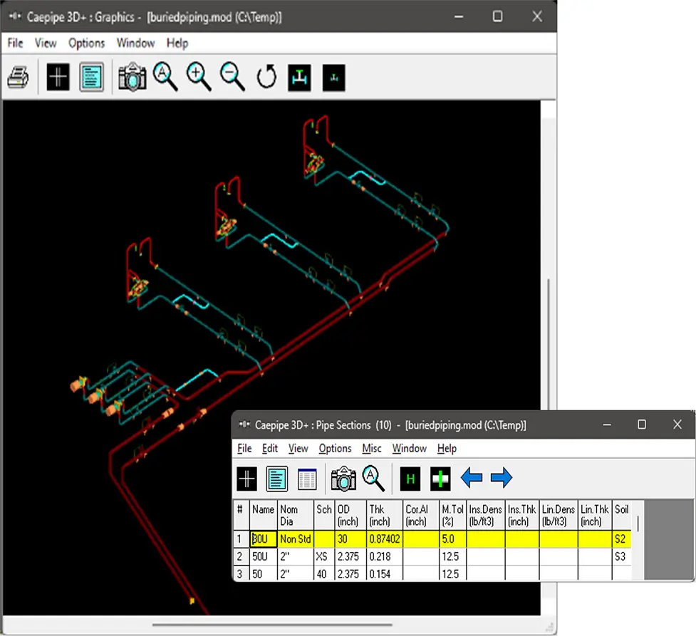
Buried Piping
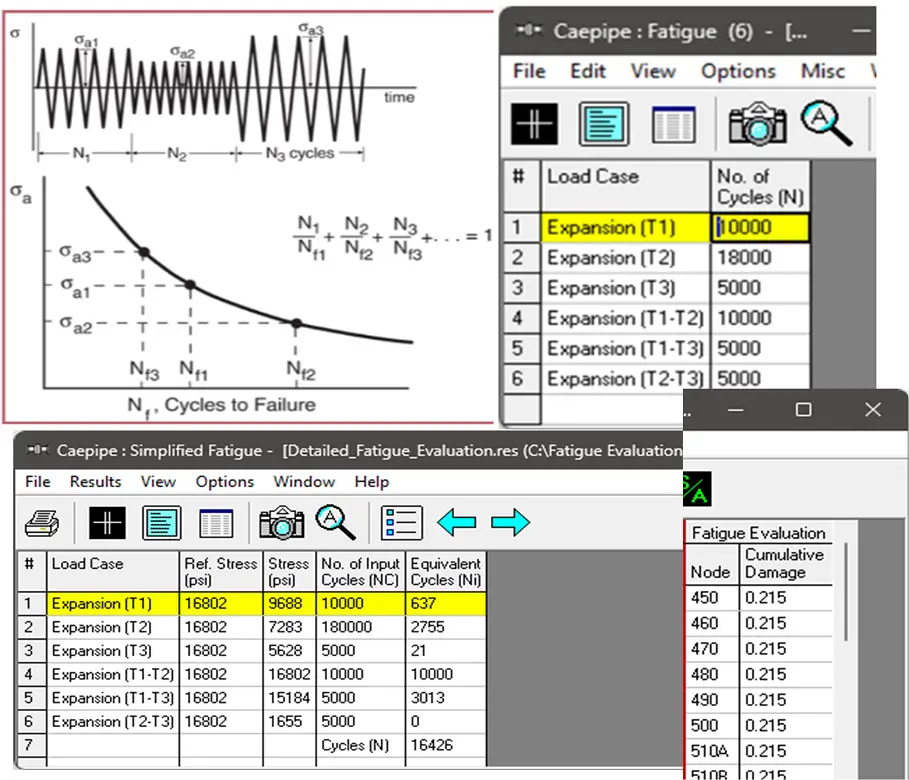
Fatigue Analysis
Static and Dynamic Analyses in one place
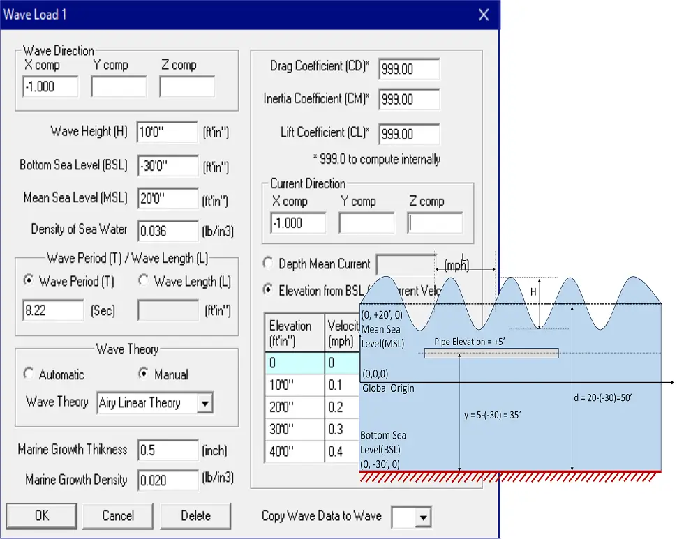
Wave Loading
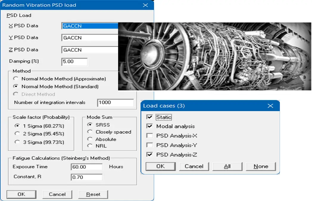
Random Vibration (Exclusive)
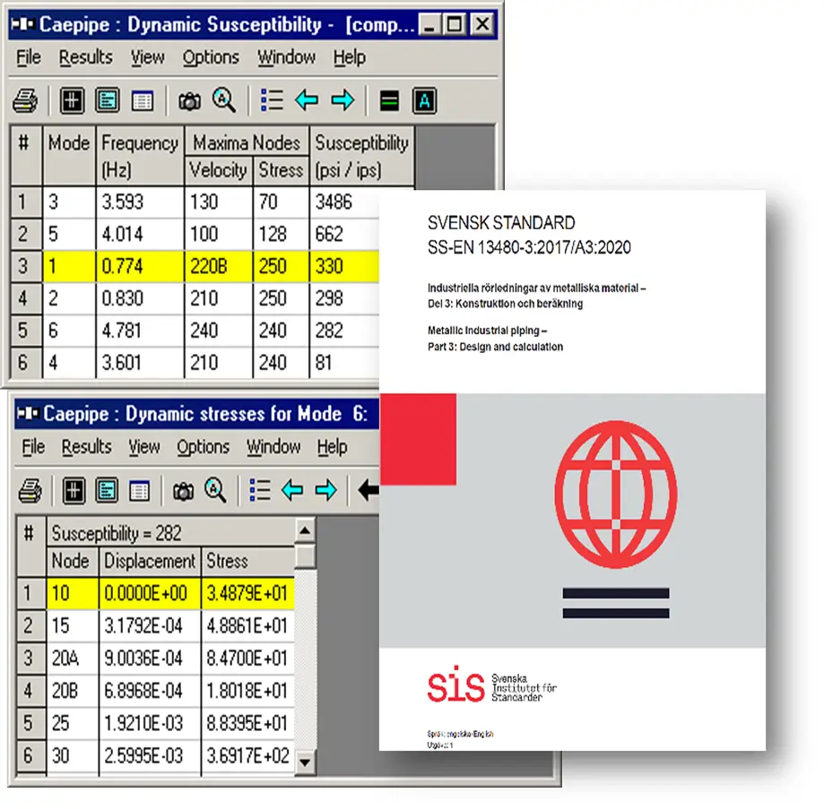
Dynamic Susceptibility (Exclusive)
Why CAEPIPE 3D+ is Distinct?
What Sets CAEPIPE 3D+ Apart?
dataTRANSLATORS from almost all 3D plant design systems (dataTRANSLATORS)
Hot-operating Clash Detection (HOTclash)
Real-time Stress Checking in CAD Systems (checkSTRESS)
Simultaneous core and jacketed pipe stress results
Buried + above-ground piping in one model
Dynamic Susceptibility: No other commercial software offers it
Auto-grouping of Load Cases: Automatically combines relevant load cases based on analysis code.
Free graphical viewer for stakeholders (Review Module)
Free Evaluation software: Up to 20 rows (Stand-alone Eval Module)
Additional Unique Features of CAEPIPE 3D+
Segmented and Directional Wind/Wave/Seismic Load Handling: Easily apply wind/wave /seismic loads selectively to model regions or directions.
Custom Fatigue Curve Import: Supports user-defined S-N curves (e.g., from manufacturer test data) for detailed fatigue evaluation.
Nozzle Flexibility Modelling: Includes vendor-defined or code-based flexibility for nozzle connections without needing external FEA.
Fatigue Check at Each Node: Node-by-node fatigue damage check using cumulative damage theory (Miner’s Rule).
Batch Analysis Mode: Automatically runs multiple what-if scenarios and outputs summary results for quick comparisons.
Integrated Report Generator: One-click generation of Formatted code-compliant PDF reports with plots, diagrams, and result tables.
Cloud Licensing Option: Available for distributed teams or consultants needing flexible access.
CAEPIPE empowers both designers and stress engineers to collaborate, validate, and optimize piping routes in real-time.
Speed and Accuracy: Where CAEPIPE 3D+ Excels
The analysis engine is built around a custom Skyline Matrix Solver, which is:
Optimized for sparse matrix structures
Capable of handling nonlinearities with minimal iterations
Not reliant on external algebra libraries
Performs static and dynamic analysis in a single run
CAEPIPE can process complex, large-scale models with remarkable speed and minimal memory footprint.
Practical Engineering Benefits
Accelerate Design Cycles: Designers can do early checks
Reduce Errors: Integrated tools like HOTclash prevent rework
Improve Collaboration: Import/export with major platforms
Streamline Reporting: Formatted, indexed, exportable reports
Support for Codes & Components: Compliance is built-in
Easy to Learn: New users can learn CAEPIPE 3D+ quickly.

Industries Served
SST provides the above solutions and services to EPC Contractors, Owner Operators and Engineering Consultants involved in the following fields.
Power Plants
Oil & Gas

Fertilizers
Sugar & Food Processing
Steel / Metal Process
Aerospace & Defense
Defense Industries
Power Plants
Oil & Gas
Fertilizers
Sugar & Food Processing
Steel / Metal Process
Aerospace & Defense
Defense Industries
Chemical Processing

Pharmaceutical

Paper & Pulp

Water Treatment
Marine & Shipbuilding
Building Services
Chemical Processing
Pharmaceutical
Paper & Pulp
Water Treatment
Marine & Shipbuilding
Building Services
What's our customer says?

The free Review module of software is always a very smart way to share the results of your calculations with your clients, so that they can view the results or print and plot them
Ing. Elio MARCUCCI
Plant Design Engineer, EM Studio, Italy.
CAEPIPE is a must-have tool for any engineer dealing with piping systems. It streamlines our work, enhances safety, and offers top-notch customer support.
J. Sridhar
Fives Cail-KCP Ltd., India
CAEPIPE is easy to use with intuitive commands and easy editing. Excellent customer support.
Pat LaPointe
PCLL Engineering Ltd, Canada
CAEPIPE 3D+ works seamlessly with our integrated PID/3D modeling system. CAEPIPE 3D+ allows our designers to interactively assess the piping configuration as they construct the 3D model of the system. This greatly speeds up the design process.
Rod Soule
ENCOREDEC, USA
The user manuals provided are very in-depth and comprehensive. There isn’t any situation I’ve encountered in my pipe stress analysis projects which has not been covered or addressed in the user’s manual.
Thomas W. Lamar, P.E
PID Engineering, USA
I have performed stress analysis using a variety of programs for over 40 years. CAEPIPE is the best stress program available and strongly urge any company to purchase it. The support team is quick to respond when needed but rarely needed.
Rusty Prince PE
Prince Engineering, Inc., USA
Our clients are spread in the following countries
CAEPIPE 3D+, the Most Disruptive Pipe Stress Software till date!
CAEPIPE 3D+ and CAEPIPE are trademarks of SST Systems, Inc. All other trademarks and trade names mentioned or used are the property of their respective owners.